
Basics for the creation of a practical Spinning Rotor Gauge were built by developing a powerless double-sided permanent magnetic bearing in Jülich in the early 1970s, which made user-friendly measruing heads with handy dimensions possible. Following overview points out achivements in Spinning Rotor Gauge history of origin.
1976
Prototype 1
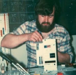
The first prototype still consisted of a loose combination of individual modules and devices: AEC-NIM cassette with magnetic bearing and drive electronics, lock-in amplifier for signal processing, frequency standard as a time base, universal counter with prescaler for measuring the rotation times, AEC-NIM -Cassette with measured value computer and a BCD strip printer. The measured value computer worked with 10-digit BCD arithmetic and a register length of 8 digits. It was based on the TMS1000 computer module, which was expanded into a programmable computer with a sequence control system developed in-house. The picture shows the author assembling the cassette for the measurement computer.
The prototype was controlled manually. First the drive had to be started, which switched off when the working speed of 400 s-1 was reached, then the gate circuit on the counter was armed and the RUN button on the computer was pressed. After about 30 s, the latter read the first value from the counter, after a further 30 s the second, and shortly afterwards the measured value appeared. The calibration factor was set with BCD coding switches on the front panel.
1978
Prototype 2
Prototype 2 largely corresponded to prototype 1, but used a BCD counter built in Jülich with a crystal oscillator as the time base and an adjustable prescaler in an AEC-NIM cassette. The measured value computer was a successor model with an extended instruction set and extended interface options. Another set of coding switches was added for offset setting for zero point correction.
1979
Prototype 3
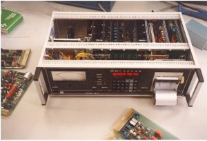
 This model was already the first step towards a series device. It consisted of an AEC-NIM frame with three cassettes: 1. Magnetic bearing electronics, 2. Drive electronics and signal processing, 3. Measurement computer. The cassette with the measured value computer contained a CPU card with the then new 16-bit microprocessor TMS9900 (clock frequency 3 MHz), 4 KB EPROM and 2 KB RAM, a counter card with 28-bit binary counter, 20-bit prescaler and crystal oscillator (1 MHz) as time base, a card with interfaces for the control panel with alphanumeric LED display and the built-in printer as well as an output card with 8-bit DA converter for the analog display.
The sphere was controlled manually on the corresponding front panel of the cassette. The computer was controlled via a keypad, which was also used to enter the parameters for the measurement. The working speed was still 400 s-1. After falling below the lower speed limit, the ball had to be raised again manually.
Another 10 copies of this prototype were built and made available to PTB and the corresponding institutes in other countries for measurements. The picture shows from the left the cassettes with magnetic bearing and drive electronics (green LEDs), next to them the measured value computer with printer, display and control panel, on the left in the foreground the vacuum apparatus with measuring head.
1981
Leybold VISCOVAC VM210 and MKS SRG-1
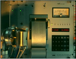
 These first commercial devices from licensees Leybold and MKS were based on the assemblies used in prototype 3 and in the pilot series, which were now integrated in a 19 ″ housing. There was also an optional RS232 interface that could be used to enter parameters, read out measured values and remotely control the raising of the ball. The only difference between the devices was the different front panel design and slightly different firmware.
In contrast to the SRG-1, the VM210 could also output the inverse measured value, so that the mean free path and the monolayer coverage time could also be displayed with the corresponding calibration factor.
The control gear of the VM210 was manufactured by RWD in Aachen, that of the SRG-1 by MKS in Munich. The associated measuring heads were manufactured by Leybold in Cologne as VK200 with its own design or in an unchanged form by MKS in Munich. The picture shows the VM210 from Leybold, to the left of it an interface and a signal processing module, in the foreground a magnetic bearing module.
1983
Leybold VISCOVAC VM211 and MKS SRG-2
 The VM10 or SRG-1 was very heavy due to the large number of modules and the large power supply unit and had no non-volatile memory, so that the parameters had to be re-entered each time it was switched on. In addition, the device did not yet have linearization, so the display error increased rapidly from around 10 Pa. A successor model was therefore presented at the international vacuum congress in Madrid in 1983, which had been improved in several ways. The electronics were combined into two assemblies, a mainboard with the control and an assembly with the measuring head functions. The device was also housed in the 19 ″ housing, but had a significantly lower power consumption (12 W) and a significantly lower weight. The new compact 16-bit microprocessor TMS9995 was used (clock frequency 3 MHz).
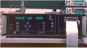
The device was marketed by Leybold as VISCOVAC VM211 and by MKS as SRG-2. It had 32 kB EPROM and 4 kB battery-buffered RAM as well as a buffer battery for the magnetic bearing, as well as two switching outputs, analog output, built-in printer, alphanumeric (VM211) or numeric display (SRG-2) and optional RS232 or IEEE488 interface. A major innovation was the fully automatic ball and speed control and a linearization function that extended the measuring range to 100 Pa. The working speed was now 415 s -1 . In addition to the pressure in Pa, mbar, or Torr and the deceleration rate in s -1 , the VM211 could also display the mass flow density, the particle flow density, the gas density, the mean free path and the monolayer coverage time. Both devices had the same structure except for the front panel and were manufactured by RWD in Aachen. The picture shows the VISCOVAC VM211.
1985
Measuring head with differential scanning coils
The measuring head, manufactured since the first series devices in 1981, was very sensitive to vibrations. This measuring head was improved in several ways in 1985: The speed scanning with differential coils resulted in a significantly higher signal yield and lower sensitivity to radial movements of the ball, improved damping coils enabled more effective vibration damping and the measuring head was now designed for production.
It also no longer had a gap between the steel jacket and the inner bore for the measuring tube, into which sensor balls could fall when trying it out and cause short circuits on the ring-shaped connection plate below. The measuring head was manufactured by MKS in the unchanged form as SH700, and by Leybold in its own design as VK201.
1989
Leybold VISCOVAC VM212
The VISCOVAC VM211 was revised again in 1989. It now used a TMS9995 with 4 MHz, instead of the built-in printer, it had a Centronics-compatible parallel printer interface and both an RS232 and IEEE488 interface as standard. A 24 V-compatible PLC interface for remote control was also new. In addition, a battery-backed RAM with an integrated clock was used so that printouts could be provided with a time stamp.
The user interface has been improved and operation has been simplified, as the operating philosophy introduced by Leybold on the VM211 did not really appeal to the user. There were also some additional functions, including measuring viscosity. The VM212 was made CE-compliant in the 1990s through minor EMC measures. After the takeover of Leybold by Balzers, the product was discontinued in 1998.
1995
SAES Getters SVG1
 The SVG1 was designed as a portable device especially for applications in the field of vacuum insulation. With this device, the 16-bit era came to an end. The SVG1 had a 32-bit MC68332 microcontroller with a clock frequency of 21 MHz, 512 kB ROM and 256 kB RAM. The entire electronics were housed on a printed circuit board. The 12 ″ housing was provided with a carrying and mounting bracket.
For the first time, a mains transformer was no longer used, the device was fed from a switched-mode power supply that accepted mains voltages of 90 to 260 V without switching. A newly developed linearization function enabled a measuring range from 10 -4 Pa to 100 kPa. (This linearization is also used in all later devices.) The completely redesigned, symmetrical measuring head had an integrated temperature measurement and a stronger magnetic field to clamp the ball. In addition, the ball was operated at a working speed of 615 s -1 , which, together with the strong clamping, gave it a high level of insensitivity to vibrations. The device was therefore also suitable for use on construction sites. Further equipment features were a built-in printer, RS232 interface, switching outputs, analog output and an interface for memory cards to save settings and measured values. The SVG1 including the measuring head was manufactured by RWD in Aachen. The picture shows the SVG1 with the control panel cover open.
1998
MKS SRG-2CE
Since the aging SRG-2 had to be replaced by a CE-compliant successor, the SRG-2CE was created, which was only similar in name to its predecessor. It was based on the SVG1 electronics, which were cut down to include the functions that were not required. The device was housed in a 19 ″ housing with only 2 height units. It was compatible with the SH700 measuring head of its predecessor and worked at a speed of 440 s -1 . The measuring range was 10 -4 to 100 Pa. Equipment features were built-in printer, RS232 interface, switching outputs and analog output. Initially, the device was still manufactured by RWD, from 1999 onwards by the author himself (KW).
2003
MKS SRG-2CE/0
After the procurement of various components and the custom-made differential transformer caused increasing problems, the electronics were redeveloped. The device now had a parallel printer interface instead of the built-in printer. The magnetic bearing no longer required a differential transformer; it used a new concept based on a measuring bridge with electronic coil replicas (gyrators).
2004
Study „atm-O-sphere“
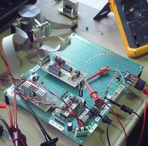 In this study, the feasibility of a continuously measuring Spinning Rotor Gauge was examined. The measuring range should extend from 10 -4 Pa to 100 kPa. A vertical, coaxial measuring tube was located in the measuring head. The stator of the drive had a laminated core. Compared to the conventional measuring head, the now three-phase motor had a high degree of efficiency.
The working speed was 700 s -1 . A reference oscillator was synchronized by a quadrature PLL to the two-channel sampled orthogonal speed signals and delivered the instantaneous speed in real time. A speed controller then kept the working speed constant. This was all implemented in software and was done by a 32-bit DSP (TMS320F2812) with a clock frequency of 150 MHz. However, the lower limit of the measuring range that could be achieved was only around 0.01 to 0.1 Pa, since smaller drive powers were lost in the noise of the stator circuit. The temperature dependency of the motor efficiency also posed a problem. The picture shows an experimental setup for commissioning the measuring head (top left).
2006
MKS SRG-2CE/ARM
With the entry into force of the RoHS directive, the MC68332 microcontroller previously used in the SRG-2CE / 0 became obsolete. This was on a purchased module. A replacement module was therefore developed using a 32-bit ARM7 microcontroller (LPC2106) with a clock frequency of 60 MHz. Since the resources of the two controllers were very different, the operating system had to be rewritten and the application rewritten. With the new operating system, an ARM7 platform was created, which later served as the basis for many new and further developments.
2008
MKS SRG-3
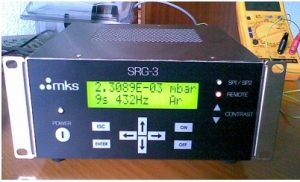 After other essential components of the SRG-2CE were difficult or impossible to obtain, e.g. B. the LVDT control module NE5521, it was time for a successor device. The result was the SRG-3 (picture), the Spinning Rotor Gauge that was completely made using SMD technology. It is a compact device in a ½-19 ″ housing. Here, too, the ARM7 microcontroller LPC2106 with 60 MHz clock frequency is used, which is ideally suited for the Spinning Rotor Gauge due to its 32-bit timer modules. The firmware is based on the operating system mentioned above.
Features include a two-line LCD display, auxiliary inputs for external transducers, USB and RS232 interfaces, parallel printer output, switching outputs, and analog output. As with the predecessor SRG-2CE, the working speed is 440 s -1 . The device is compatible with the previous SH700 measuring head, which has not been manufactured in Munich for a number of years, but in Aachen. The devices were initially only manufactured by KW in Aachen, and since 2012 also by MKS in Munich.
2011
KW VIM-1
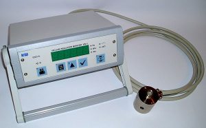 The VIM-1 is specially designed for monitoring closed vacuum spaces. It was created at the request of users of the earlier SVG1, who could no longer get a replacement for this device, which was still in use, because SAES Getters had discontinued the product after a few years. The portable device (see also cover picture) is comparable in size to the SRG-3. It also uses the same ARM7 microcontroller LPC2106 running at 60 MHz. The VIM-1, on the other hand, has modular electronics. Each measuring head function is housed on its own small plug-in module, so that, if necessary, it can be adapted to other measuring head designs simply by exchanging the relevant modules.
The measuring range is 10 -4 to 100 Pa, the expansion up to 100 kPa was waived in order to make the device more cost-effective. The measuring head has an integrated temperature measurement and is just as insensitive to vibrations as that of the SVG1, and the working speed 615 s -1 has also remained. The device is extremely easy to use. Further equipment features are USB and RS485 interfaces, serial printer output and switching output with semiconductor relay. Several devices connected to a network can be controlled from one PC via the RS485 interface.
2019
The newly founded ph-instruments GmbH under the direction of Dr. Peter Hofmann (including long-time managing director of MKS Instruments Deutschland GmbH) takes care of the continued existence of the enormous knowledge of Mr. Klaus Witthauer. The aim is to continue this unique technology together with Mr. Klaus Witthauer and an experienced team of measurement and control technicians / engineers, to develop new products and to establish them in new applications. The independence of large corporations and their existing product ranges allows the best solution to be offered to the customer and technical support …