
Vacuum instulation monitoring standard vs. SRG
Vacuum insulation monitoring standard approach
Vacuum insulation monitoring with VIM-1 SRG-Technology
Why vacuum insulation?
Vacuum insulation is the most widely used High Vacuum application. No other type of thermal insulation is so efficient and enables very thin “insulation thicknesses” compared to other technologies [1].
(Vacuum) Insulation avoids the “loss” of thermal Energy through transfer of heat into a colder area; it can be used to insulate hot/warm areas from colder ones (e.g. high temperature batteries, houses in winter, solar collectors) and vice versa (dewars, liquefied gas vessels, refrigerators, cooled superconducting magnets and wires).
Good thermal insulation is a significant factor to reduce greenhouse gases, as all forms of heat/cooling (the separation of cold / warm areas) require a great deal of energy to generate or pump the heat from one system into another; proper insulation keeps the systems separated, reduced additional work (energy) should be required thereafter to keep the areas at the same conditions (temperatures) for a long time, and works best by minimizing the room between the systems as it´s lost space (see above).
Facing energy transition vacuum insulation is furthermore improving its importance. To provide high enery density when using natural gas or hydrogen as fuel in mobile applications, it is required to introduce deep cold storage systems to provide liquified natural gas (LNG) or liquid hydrogen (LH2) at a reasonable volume.
Physics
It´s well known that heat transfer is based on three modes: convection, conduction and radiation.
![]()
Conduction and radiation can be avoided by “minimizing mechanical contacts, proper materials” and “reflect/absorb the radiation” by baffles and ophthalmic effects.
Convection relies on the presence of a “mobile species” e.g. gas molecules that are able to “store” and “transfer” heat from one to another area. A small decrease in pressure has no effect on the thermal conductivity of a gas, because the reduction in energy-carrying molecules is offset by a reduction in collisions between molecules (get faster from one area to another).
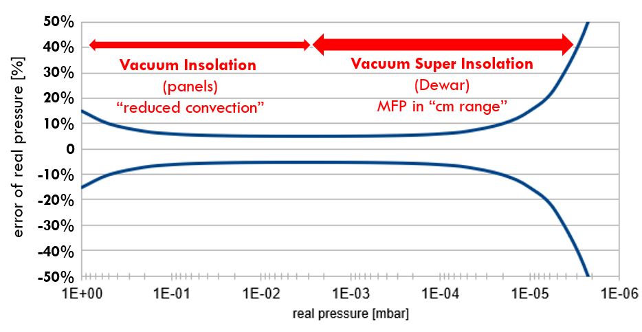
However, at sufficiently low pressure,“convection” is significantly reduced if the Mean Free Path length of molecules is longer than the diameter of surrounding walls (e.g. vessel).
In reality, typical wall distances are in the cm range, meaning the pressure should be at < 10-2mbar.
Generate Insulation Vacuum
In a first step, vacuum is generated by pumping the atmospheric gas out of the system by different types of pumps, in nearly all cases using electrical energy to run mechanical pumps. To get into the High Vacuum regime, bulky, expensive, complex and highly sophisticated pump systems are needed, using at the final stage a turbomolecular pump.
Generating and thereafter keeping a system under constant Vacuum conditions is impacted by a significant number of different physical effects like pumping diameters, form factors, flow regimes, gas and temperature dependencies, enclosed liquids with low vapor pressure, capillary effects, materials used, and finally being negatively affected by all kind of leakages.
Leakages
Leakages – like in an inverted pump and in a stationary system – will cause an increase in pressure over time. Leakages can have different causes; external leaks are obviously caused by scratches on sealing surfaces, by unavoidable permeation through elastomers and nearly invisible cracks in the material.
External leaks can occur after years of usage due to mechanical stress (temperature changes, transportation issues, material fatigue).
Internal leaks are often hard to find as no leak detector will detect them Causes can include low vapor pressure liquids (oils), out-gassing cavities , in weldings and used materials, the issue can last for long periods due to the small pumping diameter, and the effect will start again once the cavity has been restored to atmospheric pressure (and is quickly refilled…).
As many of these effects are temperature, time, geometry and surface-area related, it could be a very time-consuming effort to get into the High Vacuum area, and even more to stay there once the pumps are disconnected….
Sustain Vacuum
To run an insulation vacuum on a long term (years), chemical/physical pumps are used where possible. These types of pumps have some limited capacity and may even hide some issues once cooled down.
- Getter materials should typically absorb lighter gases like Hydrogen by chemical bonding. Hydrogen has the tendency to permeate through most materials as well as stainless steel or even desorbs out of steel. Getter materials work at room temperature and are fired before they start absorbing, the reaction is mostly irreversible.
- In the case of an insulation vacuum used for liquid and therefore cold gases, an adsorbing material with a large specific surface area can be used. The system works like a cryogenic pump. The adsorber is thermally connected to the cold part of the vessel inside the insulation vacuum. After cool down of the tank by a liquid gas, gases with a higher condensation point (than the cold liquid) get adsorbed (freeze out) and transfer into the solid state (low volume). Yes, this costs “boil of gas” and more importantly the effect is reversible: when the adsorber is heated up (an empty vessel) the gases transfer into the gas phase again…
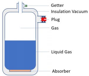
Vacuum insulated Storage system (schematic drawing)
![]()
Vacuum insulated Transfer system (schematic drawing)
Measurement of the insulation vacuum at Manufacturing
The quality of the vacuum during manufacturing is measured by one overall effect: pressure (in best case, but with other issues: “partial pressures”). The achievable base pressure is one indication of the quality of vacuum insulation chamber but affected by the pump speed of the pumps and still measured at one end of the vessel before closed. A better solution is to disconnect the pump system by valves and measure the increase of pressure over time (which may work for one well known vessel and its properties, but not for many different vessels).
Nevertheless, once the vacuum chamber is finally closed with an O-ring sealed plug, nobody knows the pressure inside and how it changes over time… To measure the pressure many different technologies are used again, with different accuracies, measurement ranges, long term drifts, mostly with an impact on the vacuum and very often at the wrong location (next to the pump system).
In the upper High Vacuum range (down to 10-4 mbar) Capacitance Manometers can be still used, below 10-4 mbar nearly all Pressure gauges are based on the Ionization or heat transfer of the remaining gas (Hot Cathodes, Cold Cathodes, Mass Spectrometer, Mirco-Piranies), all have filaments and measure the pressure indirectly (strongly affected by contamination, aging, gas dependency and generating their own vacuum…”Ion-pump”).
The only exception is the Spinning Rotor Gauge that measures the rotation frequency change of a ball rotating in vacuum, a direct measurement without any electrical, temperature effect inside the vacuum, also the signal (a frequency change) is not affected by any electronic drifts etc.
Measurement of the insulation vacuum during operation, in service or as a quality check
So far the quality of the insulation vacuum during the live time of an insulation chamber is measured indirectly by the “boil off” of the liquid gas (“the gas bill in finance”).
The boil off is an expensive and not very reliable method looking at all the different factors that impact it.
Other more direct methods would include electronics, missing robustness and suffer from long term stability. The second option is to open the insulation chamber from time to time through the plug, and measure thereafter.
This is only possible after connecting a running high vacuum pump system and wherever the plug is after installation (e.g. for a transfer line: under the roof 10m above ground)…this can cause more harm than benefit, and is not telling you something about the status/issue before.
The only exception is the use of the simple sensor tube of the Spinning Rotor Gauge that measures the pressure, without breaking the vacuum, the signal transferred by electromagnetic forces inside the insulation vacuum chamber whenever needed, robust, environmental protected, low cost and long-term stable for years. All in a compact and portable system.
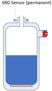
Measurement setup
The SRG Technology allows a smart 2 part design. The Sensor (a simple ball in a tube) is permanently installed at the vacuum chamber (part of Vacuum insulation vessel). On demand the Head with the Readout is mounted and through electromagnetic forces the ball (Sensor) is lifted, accelerated and used for the pressure measurement, all without breaking the vacuum and with no electronics that remain on the vessel after measurement…
SRG Installation and measurement setup
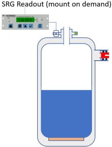
Accuracy achieved even with a non-calibrated Spinning Rotor gauge and a long term stability measured in years.
Safety/Overpressure Issue
Due to the significant volume increase if matter changes from solid/liquid state to gaseous, there is an overpressure risk related to condensed gases in an adsorber in a (more or less) closed volume. If a leak in the system caused significant amount of matter to be adsorbed, a lot of gas will be generated once the system heats up to ambient temperature (again there is no possibility other than the SRG Technology to measure the pressure, and therefore leakage, in and after operation). Depending on the volumes of the Vacuum Insulation system, overpressure can be reached (in best case the plug opens). It´s a simple calculation: each mol of previously adsorbed gas, e.g. 28g Nitrogen, expands to approx. 22,4 l gas phase, this expansion and the related gas volume increase would fill up a 22,4 l insulation vacuum chamber from vacuum pressure to around atmosphere…., assume it´s 2 mol (56g Nitrogen) frozen out over time the vessel would be at 1 bar overpressure…
[1] Ian Abley, https://www.innovationresearchfocus.org.uk/archive/IRF%2078.pdf